|
AMERICAN SOLVING INC
●
6519 EASTLAND PLAZA, BROOK PARK OHIO
(USA) ●
PH. 800.822.2285
●
PH.
440.234.7373
|

Toll Free:
1-800-822-2285
HOME PAGE
Drop Down Menu Creator by Vista-Buttons.com v5.7
Aqua Button
Generator by Vista-Buttons.com v5.0.0
Aqua Button
Generator by Vista-Buttons.com v5.0.0
|
|
AIR BEARINGS and AIR CASTERS
How Air Film Technology Works!
|
|
|
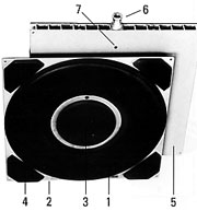
What is an Air Bearing or
Air Caster?
|
Air
Bearings are also known as Air Casters, they are one in the
same. An air caster / air bearing is made of reinforced
rubber. The circular rubber torus (bellow, item #1) is
vulcanized to an anodized aluminum back plate (item #2). When
the air bearing is deflated, the load rests on the landing pad
in the center of the module (item #3).
On larger capacity
models the air caster also includes landing pads in the the
corners (Item #4) for added support. The aluminum
back plate is bolted to a rigid load platform (item #5).
The load module top plate is an aluminum extrusion,
with a very high strength to weight ratio.
The supply of compressed air enters through a port in
the end of the module (item #6), then through the torus
(bellows) forcing a thin air film on which the load floats
with a minimum of friction.
A seal is formed between the floor surface and the
torus.
|
|
 |
|
How Air Bearings
Work?
Modules are fitted to a special
load platform or individually positioned directly under the load. In order
to achieve stability, at least three, but most often four, modules are
placed under the load. (The “three-legged stool” principle.) These are
connected through a pneumatic control unit, to a compressed air supply.
Modules should be positioned as far apart as possible in order to optimize
the weight distribution and load stability. Once the modules have been
positioned, the valves can be opened individually. The pressure in the air
bearings can be increased slowly until they lift the load and it starts to
float. The load can then be moved and be positioned exactly as required. |
|
Operation of Air Bearings / Casters |
|
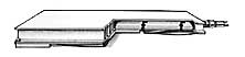
WHEN ENERGIZED
WITH A COMPRESSED AIR SUPPLY, THE FOLLOWING SEQUENCE OF EVENTS
TAKES PLACE |
|
1.) The circular reinforced
rubber bellows inflates and fills the gap between the mounting
plate and the floor. |
 |
|
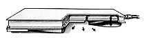
2.) As the pressure increases,
the mounting plate and its landing pads, lifts off the floor.
|
 |
|
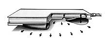
3.) When the pressure in the
bellows is higher than the counter pressure of the load, the
air flows out from the bellows forming a thin air film on
which the load floats practically friction-free.
|
 |
TECHNICAL SPECIFICATIONS
 |
|
Load |
Air Bearing |
Capacity |
Air |
Air |
Lifting |
Lift |
Support |
|
|
|
|
|
|
Module |
Element |
(lbs) |
Press. |
Cons. |
Height |
Area |
Area |
A |
B |
C |
D |
E |
|
Type |
Type |
|
(psi) |
(SCFM) |
in |
(sq in) |
(sq. in) |
(in) |
(in) |
(in) |
(in) |
(in) |
|
|
|
|
(1) |
(2) |
(3) |
|
(4) |
|
(5) |
|
|
(5) |
|
ML 8L |
ME 8L-0.3-LP |
500 |
13 |
8-24 |
3/8 |
38 |
5 |
8 |
0.83 / 1.6 |
0.39 |
1.22 / 2.00 |
0.25 / 0.75 |
|
ML 12L |
ME 12L-0.5-LP |
1,200 |
14 |
10-34 |
3/4 |
85 |
14 |
12 |
0.83 / 1.6 |
0.39 |
1.22 / 2.00 |
0.25 / 0.75 |
|
ML 8S |
ME 8S-0.6-LP |
1,000 |
26 |
11-32 |
3/8 |
38 |
5 |
8 |
0.83 / 1.6 |
0.39 |
1.22 / 2.00 |
0.25 / 0.75 |
|
ML 12S |
SE 12S-1.8-LP |
3,850 |
43 |
15-52 |
3/4 |
85 |
14 |
12 |
0.83 / 1.6 |
0.39 |
1.22 / 2.00 |
0.25 / 0.75 |
|
ML 15S |
SE 15S-2.5-LP |
5,500 |
43 |
15-61 |
7/8 |
133 |
20 |
15 |
0.83 / 1.6 |
0.39 |
1.22 / 2.00 |
0.25 / 0.75 |
|
ML 21S |
ME 21S-3.5-LP |
8,500 |
32 |
15-91 |
1 |
262 |
40 |
21 |
1.6 |
0.67 |
2.28 |
0.75 |
|
ML 27S |
ME 27S-6.0-LP |
14,000 |
32 |
15-122 |
1-1/4 |
433 |
155 |
27 |
1.6 |
0.94 |
2.56 |
0.75 |
|
ML 36S |
ME 36S-11-LP |
25,000 |
32 |
24-152 |
2 |
770 |
294 |
36 |
1.6 |
1.18 |
2.80 |
0.75 |
|
ML 48S |
ME 48S-20-LP |
45,000 |
32 |
30-182 |
3 |
1369 |
558 |
48 |
1.6 |
1.18 |
2.80 |
0.75 |
|
ML 60S |
ME 60S-30-LP |
70,000 |
32 |
46-228 |
3 |
2409 |
1042 |
60 |
1.6 |
1.22 |
2.83 |
0.75 |
|
ML 15H |
ME-15H-3.5-LP |
8,000 |
58 |
25-102 |
7/8 |
133 |
20 |
15 |
1.6 |
0.39 |
2.00 |
0.75 |
|
ML 21H |
ME 21H-70-LP |
17,000 |
63 |
27-163 |
1 |
262 |
93 |
21 |
1.6 |
0.67 |
2.28 |
0.75 |
|
ML 27H |
ME 27H-12-LP |
28,000 |
65 |
27-217 |
1-1/4 |
433 |
155 |
27 |
1.6 |
0.94 |
2.56 |
0.75 |
|
ML 36H |
ME 36H-20-LP |
50,000 |
63 |
43-271 |
2 |
770 |
294 |
36 |
1.6 |
1.18 |
2.80 |
0.75 |
|
ML 42H |
ME 42H-30-LP |
66,000 |
63 |
42-270 |
2-1/2 |
1200 |
409 |
42 |
1.6 |
1.18 |
2.80 |
0.75 |
|
ML 48H |
ME 48H-40-LP |
90,000 |
64 |
54-325 |
3 or 2 |
1369 |
1042 |
48 |
1.6 |
1.18 |
2.80 |
0.75 |
|
ML 60H |
ME 60H-60-LP |
140,000 |
64 |
81-407 |
3 |
2409 |
1042 |
60 |
1.6 |
1.22 |
2.83 |
0.75 |
|
|
1.) Air pressure in air air bearing element at capacity.
2.) Actual air consumption depends on the effective load and the
floor quality.
3.) Nominal lifting height ± .2
inches at max load
4.) Support area with
deflated air bearing module
5.) Cast aluminum load
module / Extruded aluminum load module |
AIR CASTERS
Air Film Technology
Air Bearings for Heavy Load Handling. The latest on
Air Film Technology in the Material Handling Industry. Replacement
Air Casters, Rentals, rigging equipment and Air Film Systems. Also
Wheeled vehicles with omni-directional steering for handling heavy
loads.
"Float Heavy
Loads on Air" |
| |
|
|
|
"Float Heavy Loads
on Air" |